Search the Community
Showing results for tags 'switchwire'.
-

Version 1.2.5
21,561 downloads
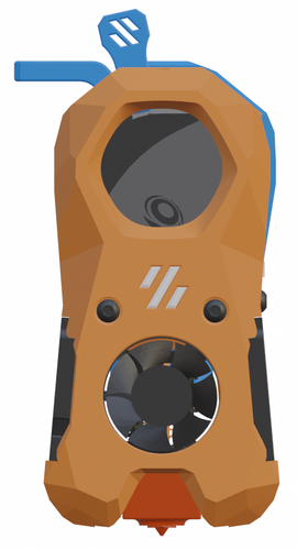
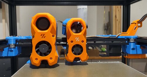
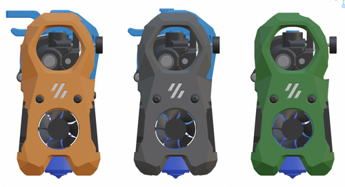
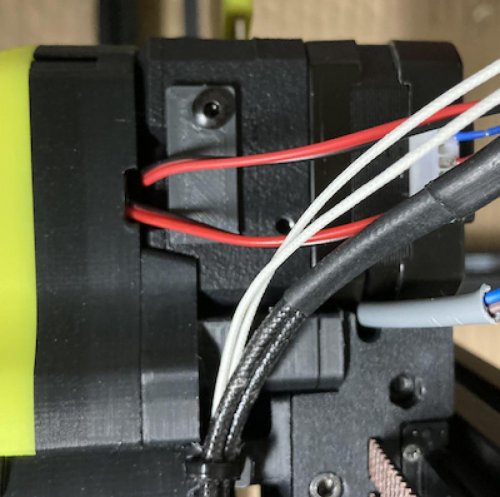
The Mini Stealth v2 toolhead is up on GitHub now. I will keep these files here as the new parts are not compatible with the v1.2.5 parts. I will support both versions in the comments here. I still need to create new assembly instructions but a lot of the steps are similar to what is described here. --------------------------------------------------------------------------- This toolhead scales down the body of the Stealthburner to a size which fits into a V0.1/V0.2. Fully assembled it weighs about 120 grams less than the original. It is designed around the Bondtech LGX Lite extruder and has versions for the Phaetus Dragonfly, Dragon and Rapido HF hotends as well as versions for the Mosquito, the Revo Voron and the Creality Spider Pro hotends. It incorporates a status LED as well as two for print visibility. I have added new stretched versions that should fit the Rapido UHF, Dragon UHF and the VolcoMosq hotends. The Dragon UHF and Rapido UHF hotends can fit in the same shroud. The UHF hotends will reduce Z travel by 8.5mm and the VolcoMosq by 3mm. I cannot verify the fitment so if there are any issues please leave a comment. There are now two hex pattern inlays based on the design by 3DP-MAMSIH and a tutorial on how to apply them to the shroud. The negative body feature of Prusa/Super Slicer can also be used to create a crop-top version of the shroud as described at the end of the tutorial. The shroud uses a pair of 4010 blowers which produce more airflow than a 5015 blower while also being notably less noisy and drawing less current. The depth of these fans do limit Y travel by 3mm on a V0.1 while the door is closed and tophat is on. The width of the main body at its base is also a very tight fit at the extremes of X travel. The shroud fits a 3010 hotend fan or a 3007 fan by using a clip-in adapter. The Mini Stealth LGX Lite fits well in a V2.4 or Trident and modified x-frame left and right pieces are included. There is a separate 'strain_relief' stl for use in the V0.1. There are also x-frame pieces that allow this Mini Stealth to be installed on a Switchwire. The nozzle is moved up by 3mm compared to the official Switchwire. The x-frame has geometry that allows a BL-Touch to fit locked between the two pieces. I have included a magnet mount and additional shroud .stl files to make this compatible with the ZeroClick mod. This toolhead also has versions that allow mounting a differential IR sensor. I have removed the mechanical Z endstop on my V0.1 and use the IR probe as an endstop and it has greatly simplified my homing sequence. There are additional x-frame pieces that allow mounting the Beacon3D probe, Euclid or Biqu MicroProbe for a V2.4, Trident or Switchwire. The included Blender file shows the entire assembly complete with screws and should answer most basic questions. Note on MGN-9 installation: The default 2mm x 10 plastic threading screw is too long for mounting the x-axis endstop. An M2 x 8 does the job fine. For mounting to the linear carriage use four M3 x 6 flat-head screws. Note: The MGN carriage shown is an MGN-9H, not the shorter MGN-9C used in the V0.1 mod. Preparation I recommend test fitting the extruder, LGX_lite_adapter_plate, PTFE tube and hotend into the shroud before running any wires to ensure that the PTFE tube length is correct and everything fits. It helps to chamfer the edge of the tube with a sharp blade so that it doesn't snag in the hotend. I is a good idea to use a file to lightly remove any printing artifacts on the mating face of the shroud. All three fans will need the wire retention piece clipped so the wires fit into the shroud channels easier. Use a small file to smooth out the break-off edges of the LED PCB and make sure the LED pockets are clear of 'droopy bits' Differential IR Probe Installation The IR Probe needs to be screwed into place with two M2.5x8 FHCS before installing any of the fans, except with the VolcoMosq or UHF hotends where the probe needs to be glued on with CA glue. The Y-offset for this probe is 4mm in front of the nozzle and the X-offset is 32mm. I strongly recommend removing the 3-pin header and soldering wires directly to the probe PCB. When installed the wires will route out from the back of the IR probe cover to then join with the hotend and fan wires. I have included a cover to allow a connector at the probe but the wire management will be less than ideal.. Assembly Instructions After pressing the status LED diffuser into place, install the right part-cooling fan first by feeding the wires through the small hole at the bottom. Then feed the wires for the status LED and hotend fan through before starting to push the LED carrier into position. Carefully push the status LED carrier as far as it will go and press the fan into position while making sure not to pinch the part-cooling fan wires. Then press the remaining LEDs into their slots. (I measure out 35mm of wire to connect these LEDs together) Here is another view also showing how the hotend fan wires fit through the hole on the side of the status LED carrier. Insert the second part-cooling fan and splice the wires together with the first fan. Install the hotend with at least two M2.5x6 screws (M3x6 for the Revo Voron). The heater cartridge should be installed away from the LEDs to avoid overheating them. ( ** don't forget the PTFE tube ) Pre-assemble the extruder pieces before installing into the shroud. Use M3x30 screws to attach motor_bridge. Install the extruder with an M3x6 BHCS on the back and then an M3x12 from below. Ensure the cables are routed as flat to the shroud as possible and secure them with zip ties. Install the strain_relief or cable_chain_mount with two M3x8 screws and the cable_door with another M3x8 screw. Close the cable door with an M3x6 screw. Use two M3x40 BHCS to secure the toolhead to the x-carriage in a V0.1/V0.2. For installation in a Trident or V2.4 use two M3x50 BHCS. Happy Printing!- 180 comments
-
- 23
-

-

-
- lgx lite
- stealthburner
- (and 19 more)
-
Version 1.2.5
13,078 downloads
The Mini Stealth v2 toolhead is up on GitHub now. I will keep these files here as the new parts are not compatible with the v1.2.5 parts. I will support both versions in the comments here. I still need to create new assembly instructions but a lot of the steps are similar to what is described here. --------------------------------------------------------------------------- This toolhead scales down the body of the Stealthburner to a size which fits into a V0.1/V0.2. Fully assembled it weighs about 80 grams less than the original. It is designed around the Orbiter 1.5 extruder and has versions for the Phaetus Dragonfly, Dragon and Rapido HF hotends as well as versions for the Mosquito and the Revo Voron hotends. It incorporates a status LED as well as two for print visibility. There are now two hex pattern inlays based on the design by 3DP-MAMSIH and a tutorial on how to apply them to the shroud. The negative body feature of Prusa/Super Slicer can also be used to create a crop-top version of the shroud as described at the end of the tutorial. I have added new stretched versions that should fit the Rapido UHF, Dragon UHF and the VolcoMosq hotends. The Dragon UHF and Rapido UHF hotends can fit in the same shroud. The UHF hotends will reduce Z travel by 8.5mm and the VolcoMosq by 3mm. I cannot verify the fitment so if there are any issues please leave a comment. It uses a pair of 4010 blowers which I found to produce more airflow than a 5015 blower while being notably less noisy and drawing less current. The depth of these fans do limit Y travel by 3mm on a V0.1 while the door is closed and tophat is on. The width of the main body at its base is also a very tight fit at the extremes of X travel. I have raised my tophat by 20mm which gives the cabling and filament tube plenty of room to breathe. The shroud fits a 3010 hotend fan or a 3007 fan by using a clip-in adapter. I have also installed this on my Trident. The included files do not address cable management on a Trident or V2.4 but do provide mounting to the MGN12 carriage. The cable chain on a Trident or V2.4 would have to be moved back at least 5mm to clear the extruder stepper motor. There is a separate 'strain_relief' stl for use in the V0.1. There are also x-frame pieces that allow this Mini Stealth to be installed on a Switchwire. The nozzle is moved up by 3mm compared to the official Switchwire due to the stepper motor being so low on the Orbiter extruder but this also allows a BL-Touch to fit into the x-frame pieces. I have included a magnet mount and additional shroud .stl files to make this compatible with the ZeroClick mod. This toolhead also has versions that allow mounting a differential IR sensor. I have removed the mechanical Z endstop on my V0.1 and use the IR probe as an endstop and it has greatly simplified my homing sequence. There are additional x-frame pieces that allow mounting the Beacon3D probe, Euclid or Biqu MicroProbe for a V2.4, Trident or Switchwire. The included Blender file shows the entire assembly complete with screws and should answer most basic questions. Note on MGN-9 installation: The default 2mm x 10 plastic threading screw is too long for mounting the x-axis endstop. An M2 x 8 does the job fine. For mounting to the linear carriage use four M3 x 6 flat-head screws. Note: The MGN carriage shown is an MGN-9H, not the shorter MGN-9C used in the V0.1 mod. Preparation I recommend using a file to lightly remove any printing artifacts on the mating face of the shroud. Use a small file to smooth out the break-off edges of the LED PCB and make sure the LED pockets are clear of 'droopy bits' All three fans will need the wire retention piece clipped so the wires fit into the shroud channels easier. Differential IR Probe Installation The IR Probe needs to be screwed into place with two M2.5x8 FHCS before installing any of the fans, except with the VolcoMosq or UHF hotends where the probe needs to be glued on with CA glue. The Y-offset for this probe is 4mm in front of the nozzle and the X-offset is 32mm. I strongly recommend removing the 3-pin header and soldering wires directly to the probe PCB. When installed the wires will route out from the back of the IR probe cover to then join with the hotend and fan wires. I have included a cover to allow a connector at the probe but the wire management will be less than ideal.. Assembly Instructions After pressing the status LED diffuser into place, install the right part-cooling fan first by feeding the wires through the small hole at the bottom. Then feed the wires for the status LED and hotend fan through before starting to push the LED carrier into position. Carefully push the status LED carrier as far as it will go and press the fan into position while making sure not to pinch the part-cooling fan wires. Then press the remaining LEDs into their slots. (I measure out 35mm of wire to connect these LEDs together) Here is another view also showing where the hotend fan wires fit. Insert the second part-cooling fan and splice the wires together with the first fan. Install the hotend with at least two M2.5x6 screws (M3x6 for the Revo Voron). The heater cartridge should be installed away from the LEDs to avoid overheating them. ( ** don't forget the PTFE tube ) Gather the wires together and secure them with the first zip-tie. (it helps to insert a snipped zip-tie through the the hole and yank it through with pliers to remove printing artifacts from inside of the channels) Loop the wire bundle back around and add in the LED and hotend fan wires. Use two more zip-ties to secure everything in place. ENSURE to leave room for the extruder by lifting the loop of wires up and out of the way as shown. More space is much better than not enough. (Don't forget the PTFE tube) Pre-assemble the extruder pieces before installing into the shroud. Use two M3x8 BHCS to install the Orbiter 1.5 extruder. It helps to have both screws in the Orbiter before putting it in place. Start the screw by the latch and then the blind screw should be easier to align. Gather all of the wires together and then use a zip-tie to secure them to the motor-bridge. Leave a little slack in the extruder wires. Install the strain_relief with two M3x6/8 screws and the cable_door with a M3x10/12 screw. Close the cable door with a M3x6 screw and screw in the extruder tensioning thumb screw. Use two M3x40 BHCS to secure the toolhead to the x-carriage in a V0.1/V0.2. For installation in a Trident or V2.4 use two M3x50 BHCS. Happy Printing!- 43 comments
-
- 12
-
-
-

-
Version 1.2.5
44,899 downloads
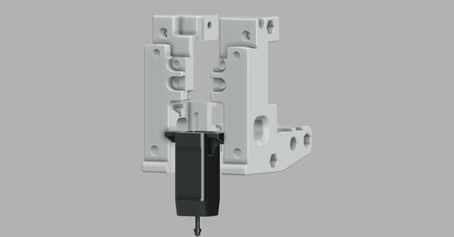
The Mini Stealth v2 toolhead is up on GitHub now. I will keep these files here as the new parts are not compatible with the v1.2.5 parts. I will support both versions in the comments here. I still need to create new assembly instructions but a lot of the steps are similar to what is described here. --------------------------------------------------------------------------- This toolhead scales down the body of the Stealthburner to a size which fits into a V0.1/V0.2. Fully assembled it weighs about 110 grams less than the original. It is designed around the Orbiter 2.0 extruder and has versions for the Phaetus Dragonfly, Dragon and Rapido HF hotends as well as versions for the Mosquito, the Revo Voron and the Creality Spider Pro hotends. It incorporates a status LED as well as two for print visibility. I have added new stretched versions that should fit the Rapido UHF, Dragon UHF and the VolcoMosq hotends. The Dragon UHF and Rapido UHF hotends can fit in the same shroud. The UHF hotends will reduce Z travel by 8.5mm and the VolcoMosq by 3mm. I cannot verify the fitment so if there are any issues please leave a comment. There are now two hex pattern inlays based on the design by 3DP-MAMSIH and a tutorial on how to apply them to the shroud. The negative body feature of Prusa/Super Slicer can also be used to create a crop-top version of the shroud as described at the end of the tutorial. The Mini Stealth uses a pair of 4010 blowers which produce more airflow than a 5015 blower while being notably less noisy and drawing less current. The depth of these fans do limit Y travel by 3mm on a V0.1 while the door is closed and tophat is on. The width of the main body at its base is also a very tight fit at the extremes of X travel. I have raised my tophat by 20mm which gives the cabling and filament tube plenty of room to breathe. The shroud fits a 3010 hotend fan or a 3007 fan by using a clip-in adapter. This Orbiter 2.0 Mini Stealth is a better fit than the Orbiter 1.5 Mini Stealth in a V2.4 or Trident as the motor no longer interferes with the path of the cable chain. There is a separate 'strain_relief' stl for use in the V0.1. There are also x-frame pieces that allow this Mini Stealth to be installed on a Switchwire. The nozzle is moved up by 3mm compared to the official Switchwire due to the stepper motor being so low on the Orbiter extruder but this also allows a BL-Touch to fit into the x-frame pieces. I have included a magnet mount and additional shroud .stl files to make this compatible with the ZeroClick mod. This toolhead also has versions that allow mounting a differential IR sensor. I have removed the mechanical Z endstop on my V0.1 and use the IR probe as an endstop and it has greatly simplified my homing sequence. There are additional x-frame pieces that allow mounting the Beacon3D probe, Euclid or Biqu MicroProbe for a V2.4, Trident or Switchwire. The included Blender file shows the entire assembly complete with screws and should answer most basic questions. Note on MGN-9 installation: The default 2mm x 10 plastic threading screw is too long for mounting the x-axis endstop. An M2 x 8 does the job fine. For mounting to the linear carriage use four M3 x 6 flat-head screws. Note: The MGN carriage shown is an MGN-9H, not the shorter MGN-9C used in the V0.1 mod. Preparation I recommend using a file to lightly remove any printing artifacts on the mating face of the shroud. Use a small file to smooth out the break-off edges of the LED PCB and make sure the LED pockets are clear of 'droopy bits' All three fans will need the wire retention piece clipped so the wires fit into the shroud channels easier. Differential IR Probe Installation The IR Probe needs to be screwed into place with two M2.5x8 FHCS before installing any of the fans, except with the VolcoMosq or UHF hotends where the probe needs to be glued on with CA glue. The Y-offset for this probe is 4mm in front of the nozzle and the X-offset is 32mm. I strongly recommend removing the 3-pin header and soldering wires directly to the probe PCB. When installed the wires will route out from the back of the IR probe cover to then join with the hotend and fan wires. I have included a cover to allow a connector at the probe but the wire management will be less than ideal.. Assembly Instructions After pressing the status LED diffuser into place, install the right part-cooling fan first by feeding the wires through the small hole at the bottom. Then feed the wires for the status LED and hotend fan through before starting to push the LED carrier into position. Carefully push the status LED carrier as far as it will go and press the fan into position while making sure not to pinch the part-cooling fan wires. Then press the remaining LEDs into their slots. (I measure out 35mm of wire to connect these LEDs together) Here is another view also showing where the hotend fan wires fit. Insert the second part-cooling fan and splice the wires together with the first fan. Install the hotend with at least two M2.5x6 screws (M3x6 for the Revo Voron). The heater cartridge should be installed away from the LEDs to avoid overheating them. (** don't forget the PTFE tube) Pre-assemble the extruder pieces before installing into the shroud. Use two M3x8 BHCS to install the Orbiter 2.0 extruder. It helps to have both screws in the Orbiter before putting it in place. Start the screw by the latch and then the blind screw should be easier to align. Gather all of the wires together with a zip-tie next to the base of the Orbiter latch and then use another zip-tie to secure the wires to the motor-bridge. Leave a little slack in the extruder wires. Install the strain_relief or cable_chain_mount with two M3x6/8 screws and the cable_door with a M3x10/12 screw. Close the cable door with a M3x6 BHCS and screw in the extruder tensioning thumb screw. Use two M3x40 BHCS to secure the toolhead to the x-carriage in a V0.1/V0.2. For installation in a Trident or V2.4 use two M3x50 BHCS. Happy Printing!- 559 comments
- 3 reviews
-
- 35
-
-
-
-
- orbiter 2.0
- v0.1
- (and 16 more)
-
Hi there. I'm at the part of the install on my Ender/switchwire conversion where I am checking the motion system. That is x and y. When I home y - all good When I home x the carriage goes from left to right but also down.... ????? When I home z it goes up ??? My probe triggers like it is suppose too. HELP! lol
-

Version 1.0.0
130 downloads
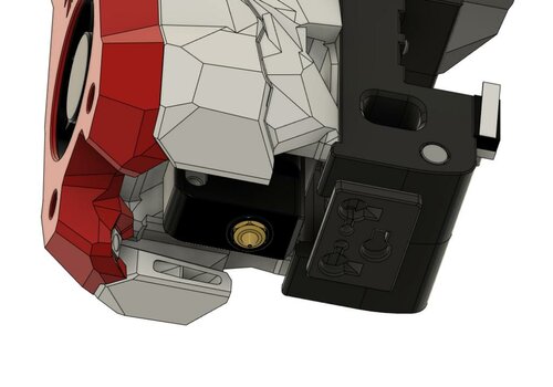
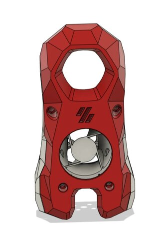
CatPaw is the ideal toolhead for Voron Zero series with Orbiter 2.0 Extruder. I developed this toolhead as I was unhappy with the existing options. The standard Voron Zero 0.2 toolhead does not provide as much cooling as I prefer, and certainly less than the StealthBurner toolhead. My design goals were also minimum loss of print volume and maximum compatibility with toolheads and options for probe and filament sensor. CATPAW: Uses Voron Zero 0.2 toolhead cartridges, so should work with all toolheads for voron Zero 0.2 (fan saver recommended) 2x 4010 Blowers, with StealthBurner duct layout for near arctic level part cooling (2x 4010 provides more air than StealthBurner toolhead) Almost no loss in print volume. X axis should be full width, loss off a millimeter or so on X if you print with your door closed. (Magnets on my door are strong enough, so the door closes again if the toolhead bumps into it, giving me the full 120x120 mm even when printing ABS Option to add the slideswipe Probe. I shortened the probe, but all other parts can be used from https://github.com/SaltyPaws/Voron_0.1and0.2mods/SlideSwipe or original repo (https://github.com/chestwood96/SlideSwipe) Option to add under extruder filament Sensor Carriages are provided for MGN7 and MGN9 X-axis rails. It is recommended to print the provided X carriage for the appropriate rail. In order to minimize toolhead height, I lowered the screw hole for the rear mounting screw. The CATPAW toolhead will work with the stock Voron Zero 0.2 Carriage, but the screw securing the X-carriage from the rear will not fit. https://github.com/SaltyPaws/CATPAW_toolhead/raw/main/images/PXL_20240101_224037977.jpg?raw=true BOM 2x SHCS (preferred) or BHSC M3x25 bolt 3x M3 nut 2x NeoPixel 1x 3010 hotend fan 2x 4010 Blower 6x3mm magnets for probe (optional) 6mm steel ball for filament sensor (optional) Omron D2F-L micro-switch with lever for filament sensor (optional) 2x M2x12 or self-tapping screw to secure micro-switch (optional) Installation Instructions Assembly should be done in the following order: Probe Solder wires to 6x3mm magnets. In order to prevent loss of magnetism, let the magnets cool against another 6x3 magnet. Press the magnets into the slots by pushing the toolhead down on a hard object. Use a large flat soldering tip at around 230C to push the magnets deeper into the slots, you want the magnets to stick out ~0.5 to 1 mm. Again, let the magnets cool down attached to other magnets to prevent loss of magnetism. Ensure wire to magnet path has very low resistance (less than 4 ohm). route wires out trough little side window. Seal hole with red gasket maker. NeoPixels Create a chain of 2 neopixels. You do not have a lot of space to hide excess cable, so make the wires between the neopixels as short as possible, while still allowing them to slide into the slots. Test the neopixels! It will be more rework to remove the hotend fan and part cooling fans later. Fans First install 3010 part cooling fan. Be very careful to only press the edges of the fan, the fan will break when pushing the center of the fan (ask me how I know...) Then proceed with installing the blower fans. Use a knife to cut the upper right hand side of the blower fan (looking back to front). This is required for routing the majority of the wires. I used superglue to keep the fan together as you will remove a fan closing latch. I accidentally cut int the fanbox, and sealed up the hole with red gasket maker. For details - see pictures below: https://github.com/SaltyPaws/CATPAW_toolhead/raw/main/images/PXL_20231225_175242278.jpg?raw=true https://github.com/SaltyPaws/CATPAW_toolhead/raw/main/images/PXL_20231225_175256608.jpg?raw=true https://github.com/SaltyPaws/CATPAW_toolhead/raw/main/images/PXL_20231225_175325632.jpg?raw=true Toolhead Cardridge Ensure the heater wires are installed pointing towards the right hand fan that has space for wire routing. Thermistor, probe and fan wires will fit on the other side (left hand side fan). Hold off on installing the zip-ties, these are best installed after the toolhead is installed on the carriage. Filament Sensor Solder wires to filament sensor (2 outer most legs). You may want to shorten the legs somewhat for an easier fit. Trim lever, so that lever does not extend past micro-switch body Install micro-switch and ball Test sensor Install Toolhead Carefully mount toolhead, ensuring that wires are not pinched, and belt is not rubbing on gantry. The bulk of the wires will go in the gap carved out on the right hand side fan, the other side will have sufficient space for probe and fan wires. Min Probe See installation instructions in orignal repo: https://github.com/chestwood96/SlideSwipe-
- 2
-
-
- orbiter 2.0
- orbiter
- (and 33 more)
-
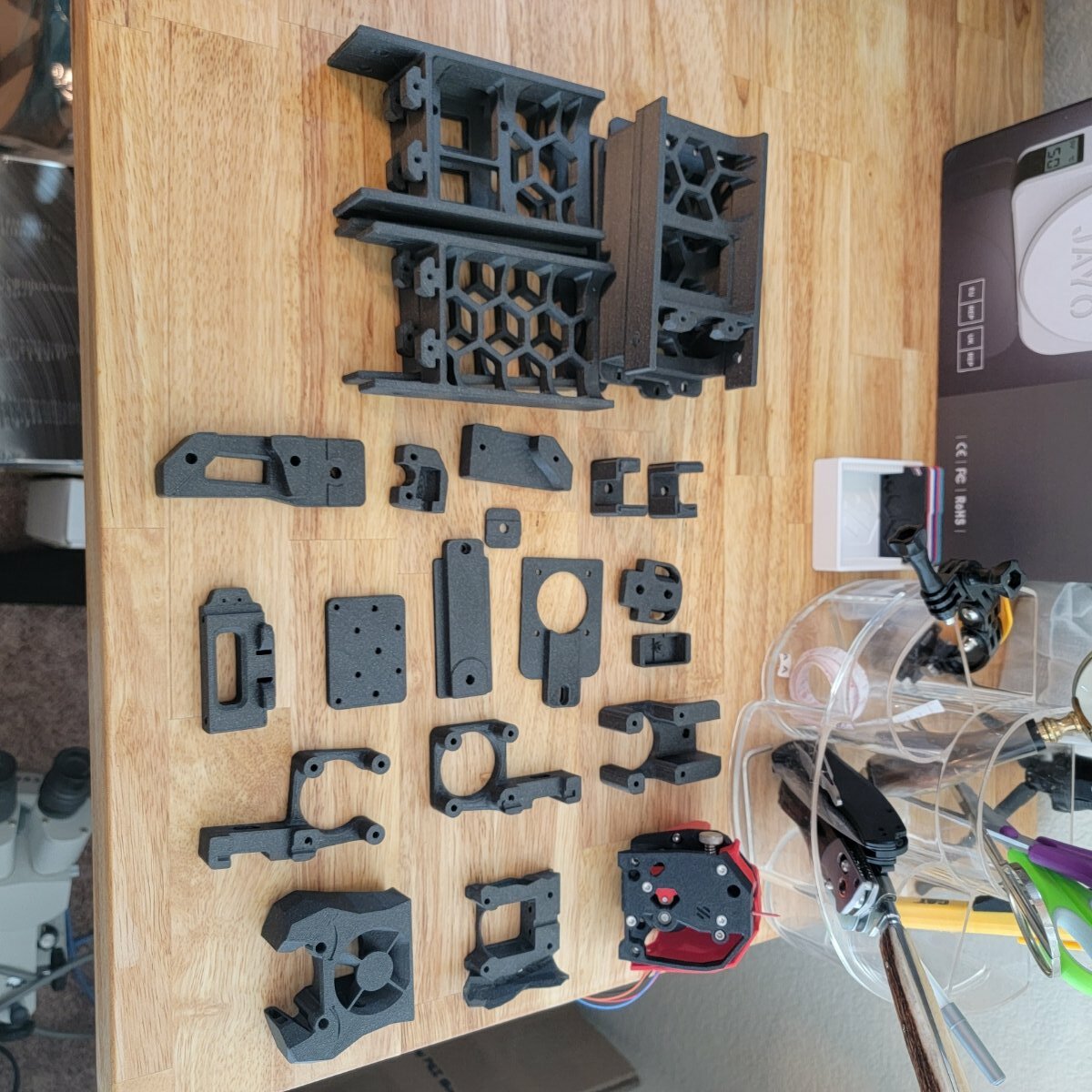
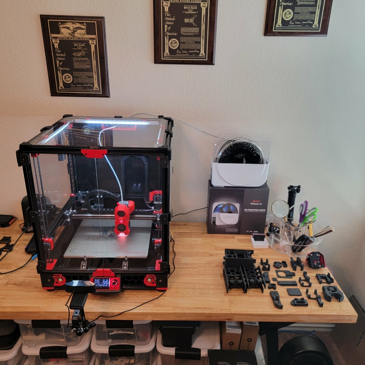
Building a bed slinger this time around. Kit is in transit. I went with Frombot3D, they did me right with my 2.4R2 build so I'm going with them again. Would have like to try the LDO kit but price and availability turned me away. I guess I will see if the savings ends up being worth it or not. So far I'm printing parts. Base parts are Prusament Galaxy Black ASA, Accent parts will be FilamentOne ASA Sky Blue.
- 70 replies
-
- 2
-
-
-
- builddiary
- switchwire
- (and 2 more)
-
Version 1.0.0
549 downloads
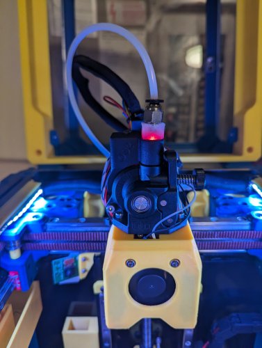
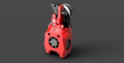
I've made a mount for the Beacon3D probe for a CW2 Switchwire I used the normal version beacon probe Mount has been tested and works great, here is a youtube short of it in action *** I've added a second mount as that moved the probe 2mm further away I wasn't happy with the original mount because as soon as the carriage got a bit melted the probe would start touching the heat block. I also believe because the probe is so close to the heater it causes the mount the deform.- 9 comments
-
- 5
-
-
- switchwire
- clockwork2
- (and 3 more)
-
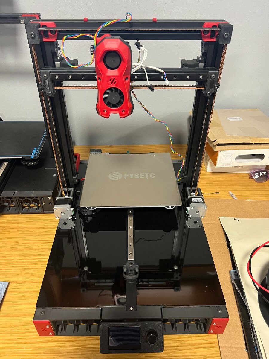
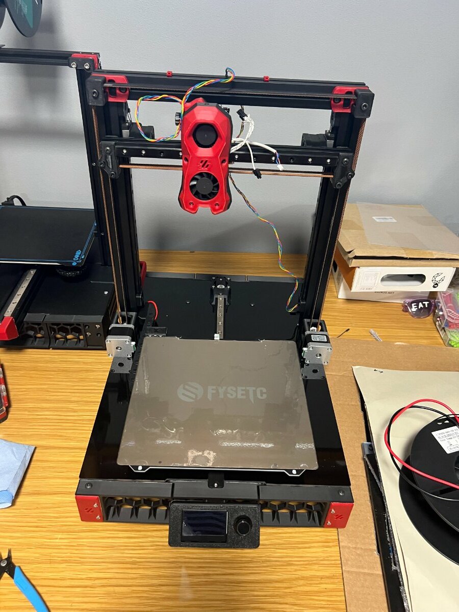
First week of Knocking my head of with fusion and the Try to Extrude some Item Profiles and doing Math on where to place what to make the Printer 100mm greater in all dimensions. Looking where i need to put how much To LEft Right and Up and Down. Oder List so far for Components : Frame Check , Holes to Drill ( i need to wait for the Cenvention Machines to get free :P) Electronics : Mainboard , PSu 24 Volt , Some stuff for Heatbed and Hotend , Cabel missing in PTFE Mechanic : all stuff together but the Rails got Delivered in MGN9 instead of 12 ( i can Curse like a Sailor in such Cases) , so need to wait till they are Delivered Things to do : STL in the Right Dimensions ( Front and Rear Grill left and Right , Some Holders for the Fly Mainboard and ather little tings) I will post if i got something ready with STL and Pictures
- 46 replies
-
- 3
-
-
- builddiary
- switchwire
- (and 1 more)
-
Version 2022.05.03
374 downloads
Stealthburner Clockwork1 PCB Cover I designed a cover for users who are still rocking the CW1 with Stealthburner, with the same low-poly esthetic of stealthburner. This cover is a snug fit, so please make sure your wiring is all nice and tidy or you could have some issues.- 6 comments
-
- 16
-
-
-
Version 2022.08.30
368 downloads
Stealthburner (RC1) Crazy Dragon Fan Duct With special thanks to @chestwood96, sponsored by @3dmellow for the Crazy heatblock, as well as the awesome base design from the VoronDesign team, I'm able to create the Stealthburner Crazy Dragon fan duct. The fan duct is designed based on the Rapido toolhead mount (RC1), retro-fitted with Dragon styled duct allowing wind to blow towards the throat only. The duct is designed to be able to mount the Phaetus/Triangle Lab dragon heatsink with Mellow Crazy Heatblock (verified by myself and @chestwood96) Phaetus Dragon UHF mini (standard UHF version without the melt zone extender) TriangleLab T Volcano (to be verified) Print Parameters Print in standard Voron settings. Previews -
Version 2023.01.20
98 downloads
MiniSB Sharkfin Modified the MiniSB toolhead to accomodate the Sharkfin extruder. -
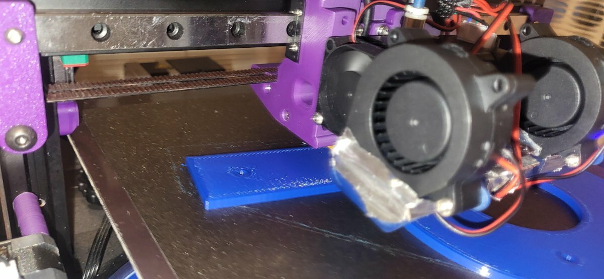
After having finished my Switchwire I'm finding it a considerable challenge getting the same layer consistency as my Voron 2.4 300. I'll post up some photos of what I'm experiencing in the hope that someone has encountered this issue and may have some insight as to how it can be improved. Stay tuned.
-
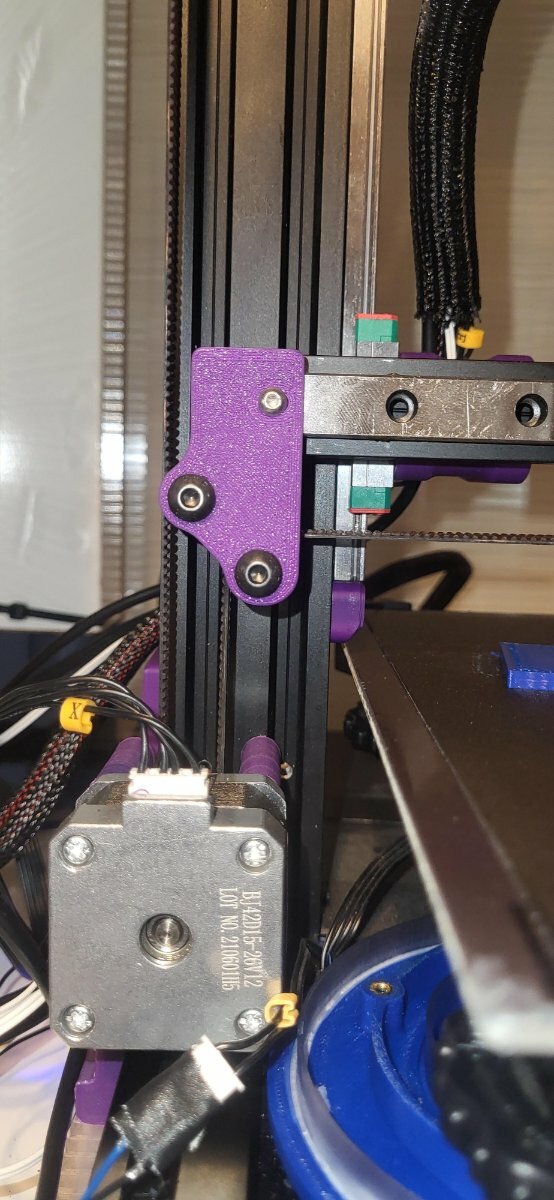
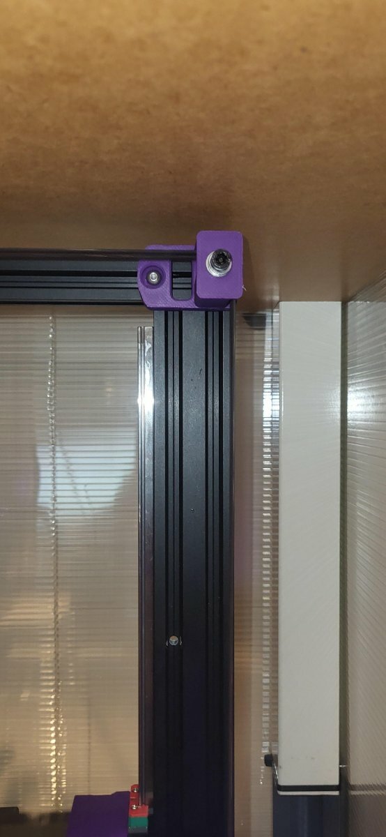
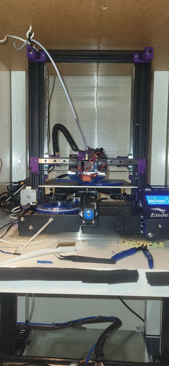
So... I´ve been super entertained during the 3 past days converting one of my smaller Cartesians (formerly an Ender 3 S1) to switchwire... After finishing my build on the V0.1 decided that one voron wasn´t enough but I didn´t really want to replace my finely tuned cartesians with a V2... next best fiddling option was install the switchwire motion system to one of the Cartesians. This has been rather budgetly (knock off omron sensor, a few screws and bolts of missing sizes from my kits, 2 meters of belt and a few idlers... all under 70 quid) redesigned the X carrier to reuse my extruder, and the machine was already fully linear railed, so it was all really cheap, quick and easy to do. Kept the original unorganised wiring as I didn´t wanted to redo harnesses and printed with leftovers of the purple used for the V0... Sorry guys no LED lights in this one. Oh. and in record time. 4 hours form the first bolt stripped to the first successfully leveled bed and first print! anyway. being that simplistic approach... I´m guessing isn´t realistic to request a serial, isn´t it? Shame she will never be for real, but she will be for me. Find a few pictures!
-
Version 2021.09.25
5,407 downloads
Cricut_Voron_Logos This repository contains vector files I have created for the Voron community and for my own Voron builds. Purpose of this repository The purpose of this repository is to share vector files that I have created for my Voron Builds. For "Voron 2.4 Build with 1 Color" Link to Cricut Design Space for "Voron 2.4 1_Color_Layer": https://design.cricut.com/landing/project-detail/6137795f68f6f90001d7abfd Link to my Repository on Github that contains all files I used to produce the "Voron 2.4 1_Color_Layer" .svg file: https://github.com/GadgetAngel/Cricut_Voron_Logos/tree/main/Voron_2.4_Logo/1_Color_Layer/Current_Design_Files For "Voron 2.4 Build with 1 Color and Without LOGO outline" with a Silhouette Layer Link to Cricut Design Space for "Voron 2.4 1_Color_Layer_WithOut_Logo_Outline_With_Silhouette": https://design.cricut.com/landing/project-detail/614501c2623cde00018a4fe6 Link to my Repository on Github that contains all files I used to produce the "Voron 2.4 1_Color_Layer_WithOut_Logo_Outline_With_Silhouette" .svg file: https://github.com/GadgetAngel/Cricut_Voron_Logos/tree/main/Voron_2.4_Logo/1_Color_Layer_WithOut_Logo_Outline/Current_Design_Files For "Voron 2.4 Build with 1 Color and Without LOGO outline" WITHOUT the Silhouette Layer Link to Cricut Design Space for "Voron 2.4 1_Color_Layer_WithOut_Logo_Outline_WithOut_Silhouette": https://design.cricut.com/landing/project-detail/614502f434e2330001c7de37 Link to my Repository on Github that contains all files I used to produce the "Voron 2.4 1_Color_Layer_WithOut_Logo_Outline_WithOut_Silhouette" .svg file: https://github.com/GadgetAngel/Cricut_Voron_Logos/tree/main/Voron_2.4_Logo/1_Color_Layer_WithOut_Logo_Outline/Current_Design_Files For "Voron 2.4 Build with 3 Colors" Link to Cricut Design Space for "Voron 2.4 3_Color_Layer": https://design.cricut.com/landing/project-detail/6137b53b0b4942000143ea8c Link to my Repository on Github that contains all files I used to produce the "Voron 2.4 3_Color_Layers" .svg file: https://github.com/GadgetAngel/Cricut_Voron_Logos/tree/main/Voron_2.4_Logo/3_Color_Layers/Current_Design_Files For "Voron 0.1 Build with 1 Color" Link Cricut Design Space for "Voron 0.1 1_Color_Layer": https://design.cricut.com/landing/project-detail/613569712ecf490001974996 Link to my Repository on Github that contains all files I used to produce the "Voron 0.1 1_Color_Layer" .svg file: https://github.com/GadgetAngel/Cricut_Voron_Logos/tree/main/Voron_0.1_Logo/1_Color_Layer/Current_Design_Files For "Voron 0.1 Build with 1 Color and without LOGO Outline" with a Silhouette Layer Link for "Voron 0.1 1Color_WithOut_Logo_Outline_With_Silhouette": https://design.cricut.com/landing/project-detail/6147bad19e2fcb000119bb71 Link to my Repository on Github that contains all files I used to produce the "Voron 0.1 1Color_WithOut_Logo_Outline_With_Silhouette" .svg file: https://github.com/GadgetAngel/Cricut_Voron_Logos/tree/main/Voron_0.1_Logo/1_Color_Layer_WithOut_Logo_Outline/Current_Design_Files For "Voron 0.1 Build with 1 Color and without LOGO Outline" WITHOUT the Silhouette Layer Link for "Voron 0.1 1Color_WithOut_Logo_Outline_WithOut_Silhouette": https://design.cricut.com/landing/project-detail/6147bc71d61aad00013c14f6 Link to my Repository on Github that contains all files I used to produce the "Voron 0.1 1Color_WithOut_Logo_Outline_WithOut_Silhouette" .svg file: https://github.com/GadgetAngel/Cricut_Voron_Logos/tree/main/Voron_0.1_Logo/1_Color_Layer_WithOut_Logo_Outline/Current_Design_Files For "Voron Switch Wire Build with 1 Color" Link Cricut Design Space for "Voron Switch Wire 1_Color_Layer": https://design.cricut.com/landing/project-detail/613bf24c5dddf60001c14fbb Link to my Repository on Github that contains all files I used to produce the "Voron Switch Wire 1_Color_Layer" .svg file: https://github.com/GadgetAngel/Cricut_Voron_Logos/tree/main/Voron_SW_Logo/1_Color_Layer/Current_Design_Files For "Voron Switch Wire Build with 1 Color and without LOGO Outline" with a Silhouette Layer Link for "Voron Switch Wire 1Color_WithOut_Logo_Outline_With_Silhouette": https://design.cricut.com/landing/project-detail/6147c7da7e75d400012c4684 Link to my Repository on Github that contains all files I used to produce the "Voron Switch Wire 1Color_WithOut_Logo_Outline_With_Silhouette" .svg file: https://github.com/GadgetAngel/Cricut_Voron_Logos/tree/main/Voron_SW_Logo/1_Color_Layer_WithOut_Logo_Outline/Current_Design_Files For "Voron Switch Wire Build with 1 Color and without LOGO Outline" WITHOUT the Silhouette Layer Link for "Voron Switch Wire 1Color_WithOut_Logo_Outline_WithOut_Silhouette": https://design.cricut.com/landing/project-detail/6147c95a2a3d570001fae277 Link to my Repository on Github that contains all files I used to produce the "Voron Switch Wire 1Color_WithOut_Logo_Outline_WithOut_Silhouette" .svg file: https://github.com/GadgetAngel/Cricut_Voron_Logos/tree/main/Voron_SW_Logo/1_Color_Layer_WithOut_Logo_Outline/Current_Design_Files For "Voron Plain Logo with 1 Color" to be used by ANY Voron Build Link Cricut Design Space for "Voron Plain Logo 1_Color_Layer": https://design.cricut.com/landing/project-detail/6137b8cce6ad93000134232e Link to my Repository on Github that contains all files I used to produce the "Voron Plain Logo 1_Color_Layer" .svg file: https://github.com/GadgetAngel/Cricut_Voron_Logos/tree/main/Voron_Plain_Logo/1_Color_Layer/Current_Design_Files For MY OWN Voron 2.4 Build Link Cricut Design Space for "Voron 2.4 QueenWithPlainVoronLogo2": https://design.cricut.com/landing/project-detail/6137e15bd254460001dad096 Link to my Repository on Github that contains all files I used to produce the "Voron 2.4 QueenWithPlainVoronLogo2" .svg file: https://github.com/GadgetAngel/Cricut_Voron_Logos/tree/main/Voron_2.4_Queen_Logo/QueenWithPlainVoronLogo2/Current_Design_Files- 3 comments
-
- 13
-
-
-
- gadgetangel
- v0
- (and 3 more)
-
-
Version 2023.01.19
143 downloads
MiniSB LGX Lite A Bondtech LGX Lite variant of the MiniSB -
Version 2021.08.24
1,890 downloads
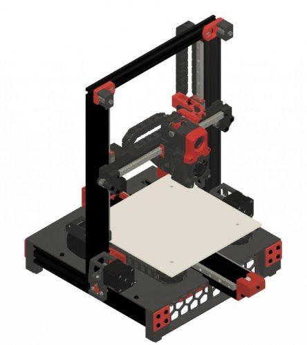
Ender 3 Pro and V2 to Switchwire Mod This is a conversion of the Ender 3 Pro and V2 to a Switchwire type coreXZ printer. My goal was to use most of the Ender 3 components while maintaining the core Voron design look and feel. Overview This mod uses most of the key components from the Ender 3 Pro (E3P) while providing a coreXZ capability. The highlights of this include: The frame is all E3P. The electronics are the stock Switchwire ones, but the E3P 24V power supply is used. I wanted to get all the electronics under the deck as this follows the Switchwire design. I had to get a little creative with the mounts to make this work. I did not include the LCD display. Mainsail (MainsailOS) is so amazing, I never use the LCD on the Voron 2.4 so I left it out. It can easily be added. The deck is easily printed in 4 sections. The XZ and gantry are slightly modified from the Switchwire baseline. The X axis rail is 300mm and is a tight squeeze on the shortened 2020 extrusion. I wanted to keep the standard rail length in case I wanted to build a stock Switchwire. The Y axis uses 2 rails. I liked the look of it and it seemed more stable that way. It also simplified the Y belt routing through the extrusion. I also removed the springs on the bed corners and replaced them with spacers. The spacers come off the E3P V-wheels. With the bed mesh probing, this seemed like a better approach than worrying about the bed changing positions if the knobs rotated/loosened. This configuration also worked without too much modification to the stock E3P wire lengths. The E3P motors can be reused if you can pull off the gears. Thingiverse has a printable gear puller (I haven't tried it). Images / CAD I have included several images and the Fusion 360 CAD model. CAD files and images are included in the repository BOM A BOM has been added that is based on the baseline Switchwire. This will not be perfect as the Ender 3's get a lot of mods by their owners. It should help with most of the key items to make the MOD. Firmware: Use the baseline Switchwire configuration available in the Voron-Switchire repository. The Voron-documentation has excellent instructions for making the adjustments. STL Files This mod uses a combination of original Switchwire and modified parts. Most of the parts are modified/new as the Switchwire and Ender 3 frames are much different. I kept all the Voron naming conventions to provide consistency. The following is a listing of the STL files, organized by location: Deck: [a]_deck_y_chain_anchor deck_front_right deck_front_left deck_rear_right deck_rear_left Electronics: [a]_ps_clamp [a]_ps_hanger [a]_rpi3_mount [a]_rpi3_shelf [a]_rs_25_hanger [a]_skr_mini_e3_mount 2020_ziptie_clip (quantity as required to suit your wiring organization) Grill: [a]_grill_endcap_x4 grill_front_left grill_front_right grill_rear_left grill_rear_right XZ-Axis: [a]_xz_cable_cover keybak_mount_plate_a keybak_mount_plate_b x_motor_mount_a x_motor_mount_b xz_block_left_a xz_block_left_b xz_block_right_a xz_block_right_b z_bearing_block_left z_bearing_block_right_generic z_carriage_stop_x2 z_motor_mount_a z_motor_mount_b [a]_xz_tensioner_x2 ** [a]_upper_idler_support_b_right ** [a]_upper_idler_support_b_left ** upper_idler_support_a_right ** upper_idler_support_a_left ** keybak_gantry_anchor ** keybak_idler_bracket ** Y-Axis: [a]_y_axis_anchor_x2 [a]_y_axis_frame_chain_anchor [a]_y_axis_ls_mount [a]_y_front_belt_mount [a]_y_front_belt_slider [a]_y_motor_mount_a [a]_y_motor_mount_b y_axis_bed_carriage Misc: 2020_MGN12_guide_x2.stl ** 4040_rail_tool ** Denotes STL files that have not been modified from the baseline Switchwire design and are located in the Switchwire repository- 6 comments
-
- 3
-
-
- triano
- switchwire
- (and 2 more)
-
Hi guys, here is the current status of my build, im waiting for the cable chains to proceed with the eletronic wiring. The plan is also to use a octopus v1.1 + ebb36 for the toolhead, while crimping i decided to remove most of the cables and can is the way to go. Self sourced parts, and a fermio enclosure.
-
Version 2022.09.23
96 downloads
LGX stealthburner connector cover This is a remix of craxoor's Afterburner PCB Cover designed to work with the Stealthburner and Bondtech's LGX Extruder.- 1 comment
-
- 3
-
-
- sammynorway
- v1.8
- (and 3 more)
-
Version 2021.08.22
332 downloads
LoudOwl aka Stabby This is alternative part cooling fan solution which uses dual 5015 fan setup for Afterburner Toolhead. Replaces original parts that house 4020 fan or any other similar type of mod. This mod is more of situational add on for PLA or similar type filaments which might require a lot of cooling (or printing at super high speeds). It is not constant solution as it increases gantry weight. Hardware 2x 5015 24v fans 1x M3x20 SCHS (DIN912) Printing There are two sets of STLs. One with inbuild supports and one without (for those who trust their slicers autosupports). Tested with recommended settings for Voron parts: 4 perimeters, 5 tops/bottoms, 40% infill. Though it is possible to use less plastic to reduce weight of plastic parts: 3 perimeters, 3 tops bottoms, 15-25% infill. Both versions of STL were tested by printing and assembling !!! Assembly First print out- 2 comments
-
- 1
-
-
- baltojikale
- v1.8
- (and 2 more)
-
Morning I have a few questions about a dual y mod on my SW Project. 1 decision I am u sure with : I will use 3 rails with 2 belted rails on the outside ( there comes the first problem) but my original idea was to use 1 wagon mgn12h in the middle and 2 on each rail right and left. After puzzling the beginning I did see that 2 wagons are to much cause I wouldn't reach the full 310x310 dimension of my print area. Question now : would 1 rail Waggon be enough on each rail ( as bed carrier I used a custom made printed carrier with the holes from the mk52 one) I hope someone enlights me. Greeting Ropey
-
Version 2021.10.09
439 downloads
Afterburner LGX Useful links, info, and models for using the The LGX™ Large Gears eXtruder with Afterburner... Afterburner LGX Mounts Klipper config Extra LGX Models LGX Cable Cover LGX Gear Cover LGX Lever Cover Afterburner LGX Mounts Mounting the LXG to AfterBurner requires some additional mounting plates. You will need both of @Nemgrea's mounts from Discord: lgx_AftB_Mount_Front.STL (Discord file link) lgx_AftB_Mount_Rear.STL (Discord file link) These models are pinned in the #voronuser_mods channel on Discord, and can be found in this message. Thanks to @Nemgrea V2.199 V0.000 and the crew for their efforts designing and testing the mounts, and offering them to the community. Aside: For my own build, I found that my third-party M3x20 screws had a large enough head that the toolhead couldn't mount to the X Carriage assembly properly without a bit more clearance. If you find yourself in this situation, this mod of @Nemgrea's mount is nearly identical to the one on Discord but with slightly more clearance for the bottom screws. Please try the (semi)official one first before using this mod Klipper config Bondtech has some official documentation for configuring Klipper here. Below is the configuration I am currently running. rotation_distance: 8 microsteps: 16 full_steps_per_rotation: 200 # use either # gear_ratio: 44:14, 37:17 # rotation_distance: 55 # or # rotation_distance: 8 # but not both! The either...or warning is not from Bondtech, but provided here to honor the memory and sacrifice of my first hotend and save those that may come after from suffering the same fate... Extra LGX Models LGX Cable Cover Besides the mounting parts, most people end up asking about a cable cover. There are a few posted around Discord, but after seeing Craxoor's PCB cover I designed a similar cover from scratch for use with the LGX. Note that this cover does not work with the toolhead PCB - it just looks similar. lgx-cable-cover.stl (Cereal not included) LGX Gear Cover A little cover for the Large Gears on the LGX so it doesn't chew through the fan wires. lgx-gear-cover.stl LGX Lever Cover Drop-in replacement for the filament pre-tension lever, in case you want a different color: lgx-lever-cover.stl- 6 comments
-
- 6
-
-
-
- geoffreyyoung
- v1.8
- (and 3 more)
-
Version 2022.10.11
112 downloads
Voron Switchwire StealthBurner CR Touch Mod This repo contains the STL for Voron SW SB CR Touch Mod. I used the SB 1.05Beta during development. But it should work on the SB v1 release as it's only X rail carriage. The STL is only for MGN12 Carriage for SW No supports are needed during the print No tools are needed to fit the CR Touch, it's a press fit I used Dragon Standard hotend for deciding height of CR touch and it's 2mm above the nozzle when pin is up It should work with other hotends as well (Hotends of same form factor as Dragon) Preview of how CR Touch Fits in the SB X rail carriage: Thanks to Voron Developers for building rocket making tools -
Version 2022.03.16
470 downloads
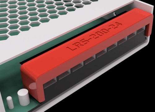
LRS Screw Terminal Cover Designed to cover the screw terminals for several LRS style PSUs. Other Meanwell PSU may work. Feel free to ping me in discord to add to the compatibility list below. Pro tip: These are very snug to the point it will bow. This is intentional as it was designed to take some effort to take off. Printing Default voron settings No supports needed Compatibility List LRS-50 LRS-200 -
Version 2022.11.18
458 downloads
Stealthburner Rapido UHF A mod that stretches the Stealthburner Front and Rapido Toolhead Front for use with a Rapido UHF configuration. It moves the lighting and cooling to Stealthburner stock locations relative to new nozzle location. Designed from SB RC1 using this version. No additional parts required. Assembly is as per Voron Stealthburner manual. You may need to increase the length of one of the LED wire legs.-
- 12
-
-
- bythorsthunder
- v2.4
- (and 2 more)